| Name | Function | |
|---|---|---|
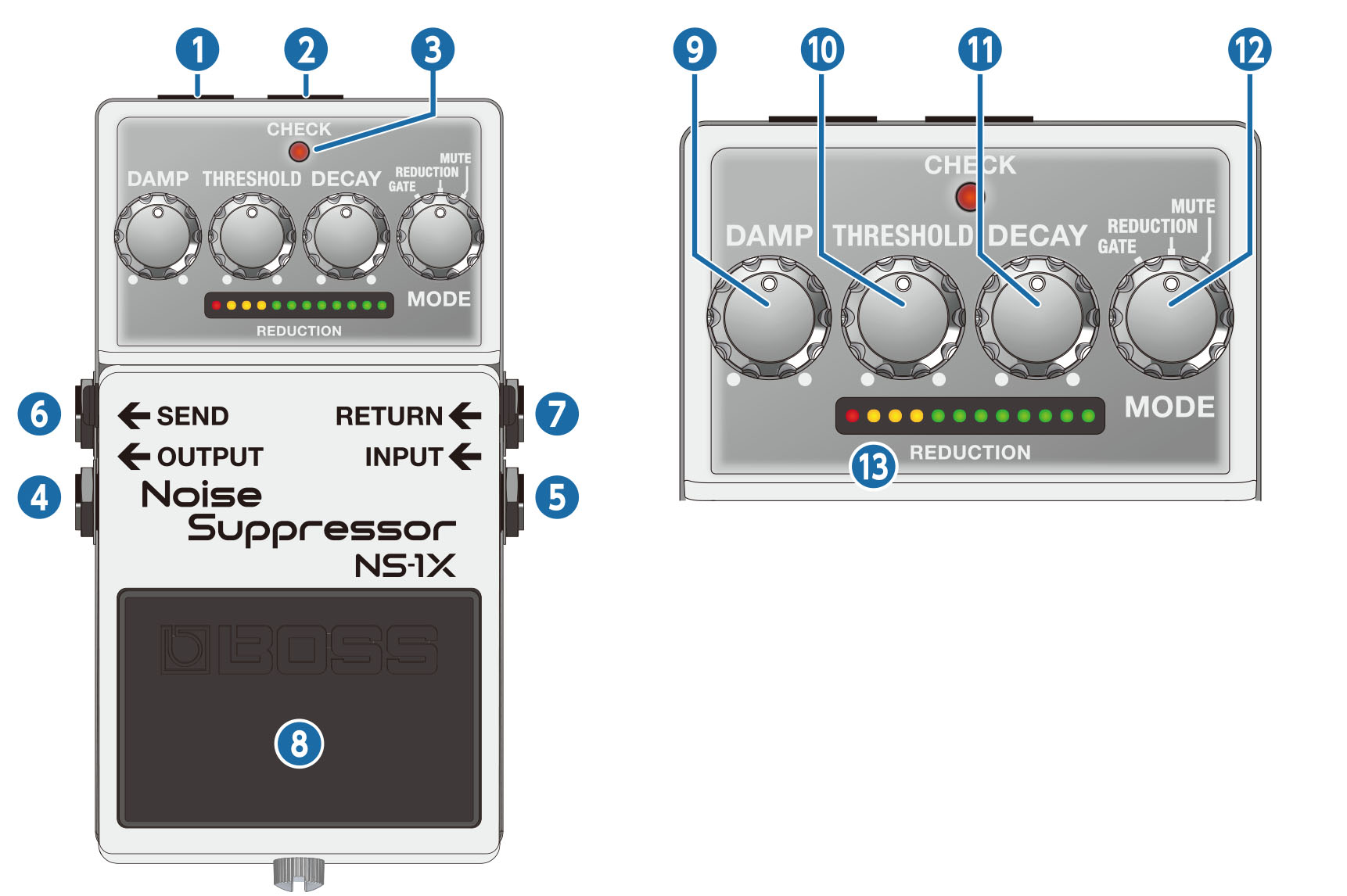
| 1 | DC OUT jack |
When using an AC adaptor, you can connect the PCS-20A parallel DC cord (sold separately) to supply power from this unit to another 9 V effect unit.
|
|
2 |
DC IN jack | Accepts connection of an AC Adaptor (PSA series; sold separately). By using an AC Adaptor, you can play without being concerned about how much battery power you have left.
|
| 3 | CHECK indicator | This indicator shows whether the effect is on/off, as well as the mute on/off status and battery check indication.
|
|
4 |
OUTPUT jack | Connect this jack to your amplifier or effect unit. |
|
5 |
INPUT jack |
Connect the output of your electric guitar, other musical instruments or effect units to this input jack. Use a 1/4” phone type (TS) Ð 1/4” phone type (TS) cable to connect to this jack.
|
| 6 | SEND jack | The signal that’s input to the INPUT jack is sent to other effect units through this jack. Connect an effect unit here for which you want to suppress noise such as distortion. |
| 7 | RETURN jack | Use this jack to receive the input signal from the effect unit for which you want to suppress noise such as distortion. |
|
8 |
Pedal switch | This switch turns the effect on/off. In mute mode, this switches between reduction and mute. |
| 9 | [DAMP] knob |
Adjusts the amount of the gate and reduction effects. When this knob is turned all the way clockwise, the effect’s attenuation is at maximum, which clearly distinguishes between the sound you’re playing and the silence. This is optimal when you want the silence to be dynamically distinct. Turning the knob counterclockwise reduces the effect’s attenuation, making the difference between the sound you’re playing and the silence smoother. This is optimal when you are playing softly, such as during more delicate passages. |
|
10 |
[THRESHOLD] knob | Adjusts the signal level at which the gate and reduction effects start. Turn this counterclockwise to make the effect activate at lower input signal levels. Turn this clockwise if there is a lot of noise, and turn this counterclockwise if the noise is not as noticeable. |
|
11 |
[DECAY] knob | Adjusts the time it takes for the sound to attenuate when the input signal level falls below the threshold level. Turn the knob clockwise for a longer attenuation time (decay time). Normally, this should be set all the way counterclockwise. |
| 12 | [MODE] knob | Switches the mode.
|
| 13 | REDUCTION indicator | Indicates the strength of the gate and reduction effects. A stronger effect attenuates the sound more, making more indicators light up. All indicators light up when mute is on. |
 WARNING
To prevent malfunction and equipment failure, always turn down the volume, and turn off all the units before making any connections.
Do not use connection cables that contain a built-in resistor.
Turning the power on/off
Once everything is properly connected, be sure to follow the procedure below to turn on their power. If you turn on equipment in the wrong order, you risk causing malfunction or equipment failure.
- Before turning the unit on/off, always be sure to turn the volume down. Even with the volume turned down, you might hear some sound when switching the unit on/off. However, this is normal and does not indicate a malfunction.
Turning the power on
Turn on the power to your amp last.
Turning the power off
Turn off the power to your amp first.