The OSCILLATOR section features an oscillator (hereafter “OSC”) with variable pitch (frequency). The OSC generates the basic waveform used as the sound source for the synthesizer.
Waveform |
Waveform characteristics |
Harmonic structure |
|---|---|---|
|
Sawtooth wave (Sawtooth)
|
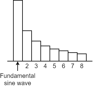
Sawtooth waves are composed of a fundamental sine wave and the sine waves of the integer harmonics, all at a fixed ratio. The way that these waves are structured is shown at the graph at right. The wave includes the nth harmonic at a volume of 1/n, with the fundamental wave considered as “1”. |
|
|
Square wave (Square)
|
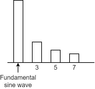
Square waves are composed of a fundamental sine wave and the sine waves of the odd-numbered harmonics, all at a fixed ratio. For the nth harmonic, the sine waves are included at a ratio of 1/n, the same as for the sawtooth wave. However, the even-numbered harmonics are left out entirely. |
|
|
Asymmetrical square wave
|
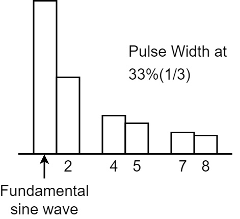
For asymmetrical square waves, the harmonic composition changes greatly depending on the ratio of the upper and lower widths. These waveforms characteristically drop the nth harmonic series is dropped when the upper width is 1/n that of the entirety. The graph at right shows that with a width of 1/3 (33%), the third, sixth and ninth harmonics are dropped. |
|


[RANGE] knob
This knob switches between frequency ranges for the oscillator.
By switching the settings from 64′ all the way down to 2′, you can change the tonal range in octaves.
When this is set to 8′, the pitch of the lowest C (keyboard pad [2]) is equivalent to middle C (MIDI note number: 60) on a piano (with Transpose set to “0”).
|
You can turn the [RANGE] knob while holding down the [SHIFT] button to alter the pitch within a ±1 octave range (this works as a FINE TUNE knob). |

Setting the pulse width control source (PWM SRC)
What’s “pulse width”?
A square wave whose upper and lower widths are not the same is called an “asymmetrical square wave”. “Pulse width” refers to how wide the upper width is compared to the entire wave, expressed as a percentage.
The harmonic structure changes greatly depending on this value, as does the sound.
This pulse width is used at a fixed preset value, but you can apply time-based changes to the pulse width with the LFO or envelope generator signal.
This is called “pulse width modulation” (PWM).
Use the PWM source switch to select whether to set the pulse width to a fixed preset value (“NAn”) , or to apply time-based changes using the LFO (“LFO”) or envelope generator (“Env”) signals.
Hold down the [SHIFT] button and press the [PWM SRC] pad.
Turn the [TEMPO/VALUE] knob to edit the value.
Value
Explanation
Env Changes by the signal of the envelope generator over time.
Use the PWM DEPTH parameter to adjust the depth of the effect.NAn Specifies a fixed value, set in PWM DEPTH.
LFO Changes by the signal of the LFO over time.
Setting the pulse width value or modulation (PWM DEPTH)
Here’s how to set the pulse width value and modulation depth.
- Hold down the [SHIFT] button and press the [PWM DEPTH] pad.
Turn the [TEMPO/VALUE] knob to edit the value.
Value
Explanation
0–255
Sets the pulse width value when PWM SOURCE is “NAn”.
When using the “LFO” or “Env” setting, this adjusts the modulation depth.
Creating original waveforms for the oscillator (OSC DRAW)
Ø Creating original waveforms for the oscillator (OSC DRAW)
Chopping a waveform and emphasizing its harmonics (OSC CHOP)
Ø Chopping a waveform and emphasizing its harmonics (OSC CHOP)
[LFO] knob
This knob adjusts the modulation intensity, when you use the modulator signal from the LFO section to control the fundamental frequency (pitch) of the OSC.
The method of change depends on the setting of the [WAVE FORM] knob in the LFO section.
Mixing the output from the oscillator (source mixer)
Four waveforms are always output from the OSC, and you can mix their levels in the ratio you like. The source mixer output is sent to the FILTER section.
Controller |
Explanation |
|---|---|
|
[ |
Adjusts the level of the square wave or the original waveform you create using OSC DRAW. |
|
[ |
Adjusts the level of the sawtooth wave. |
[SUB] knob |
Adjusts the level of the sub oscillator. |
[NOISE] knob |
Adjusts the level of the noise. |
 (square wave)] knob
 (sawtooth wave)] knob
Selecting the output waveform for the sub-oscillator (SUB OCT)
This shows how to select the sub-oscillator output waveform.
- Hold down the [SHIFT] button and press the [SUB OCT] pad.
Turn the [TEMPO/VALUE] knob to edit the value.
Value
Explanation
-2o.A -2 octave asymmetrical waveform -2oc -2 octave symmetrical waveform -1oc -1 octave symmetrical waveform
Selecting a noise output waveform (Noise Mode)
Here’s how to select the noise output waveform.
Hold down the [SHIFT] button and press pad [15] (MENU).
Use the [TEMPO/VALUE] knob to select “nS.Nd” (Noise Mode), and press pad [2] (ENTER).
Turn the [TEMPO/VALUE] knob to edit the value.
Value
Explanation
Pink
Pink noise
ľhit
White noise