ASSIGN 1–20
For each parameter, you can specify, in detail, which controller will control which parameter. You can create 20 sets of such assignments.
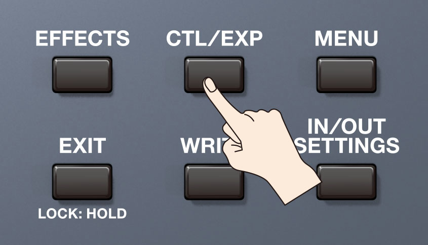
- Press the [CTL/EXP] button.
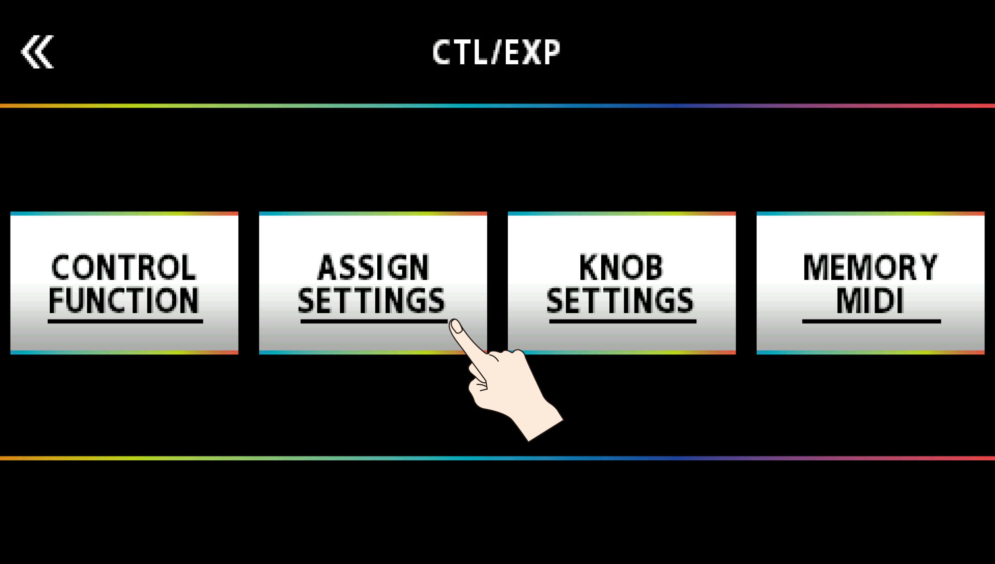
- Touch <ASSIGN SETTINGS>.
The ASSIGN SETTING screen appears.
- Turn the [SELECT] knob to select ASSIGN NUMBER (NUM).
Turning the knob will move the selected item vertically.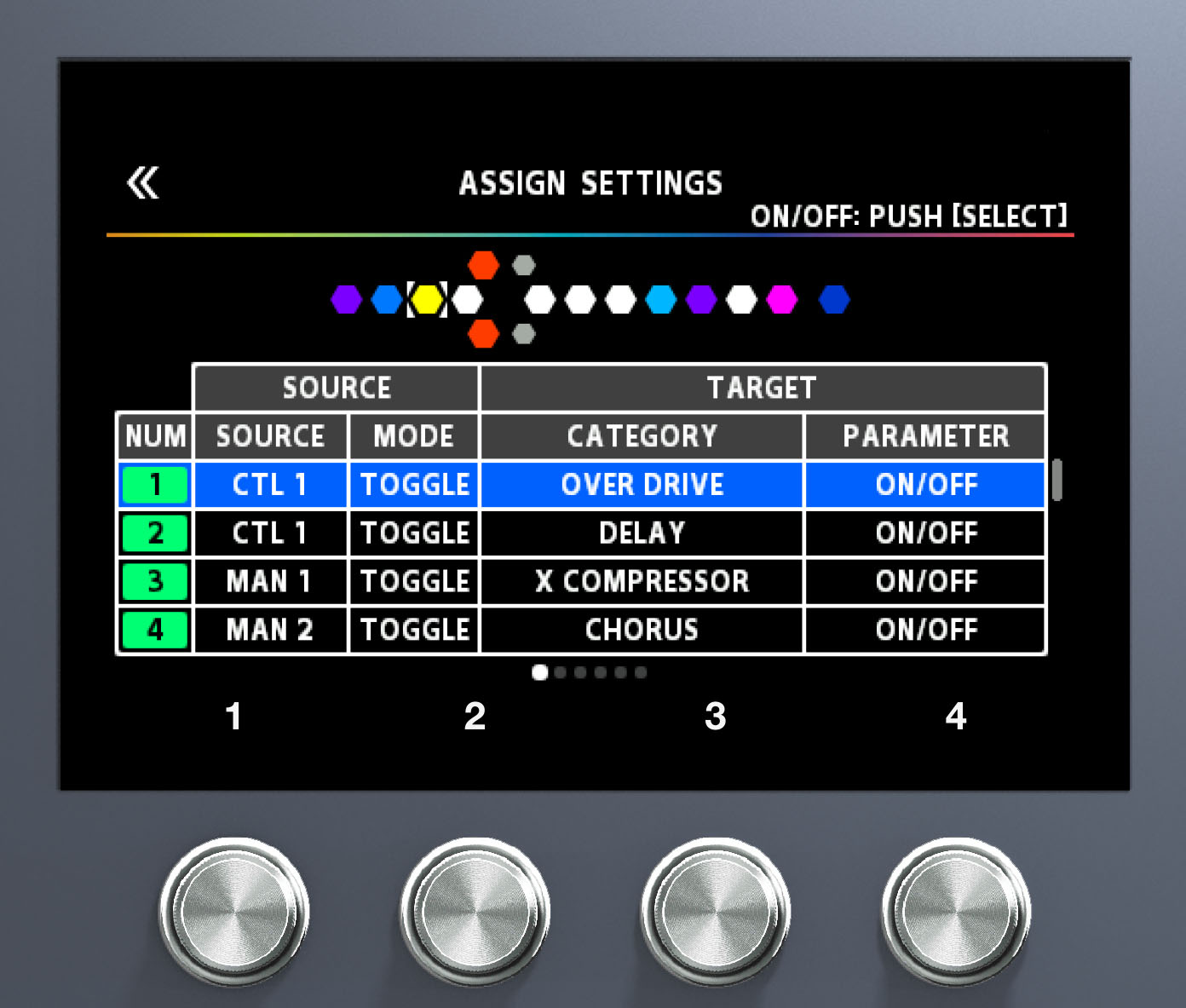
Use knobs [1]–[4] to select parameters or edit the values. Switch between pages using the PAGE [÷] [ø] buttons.
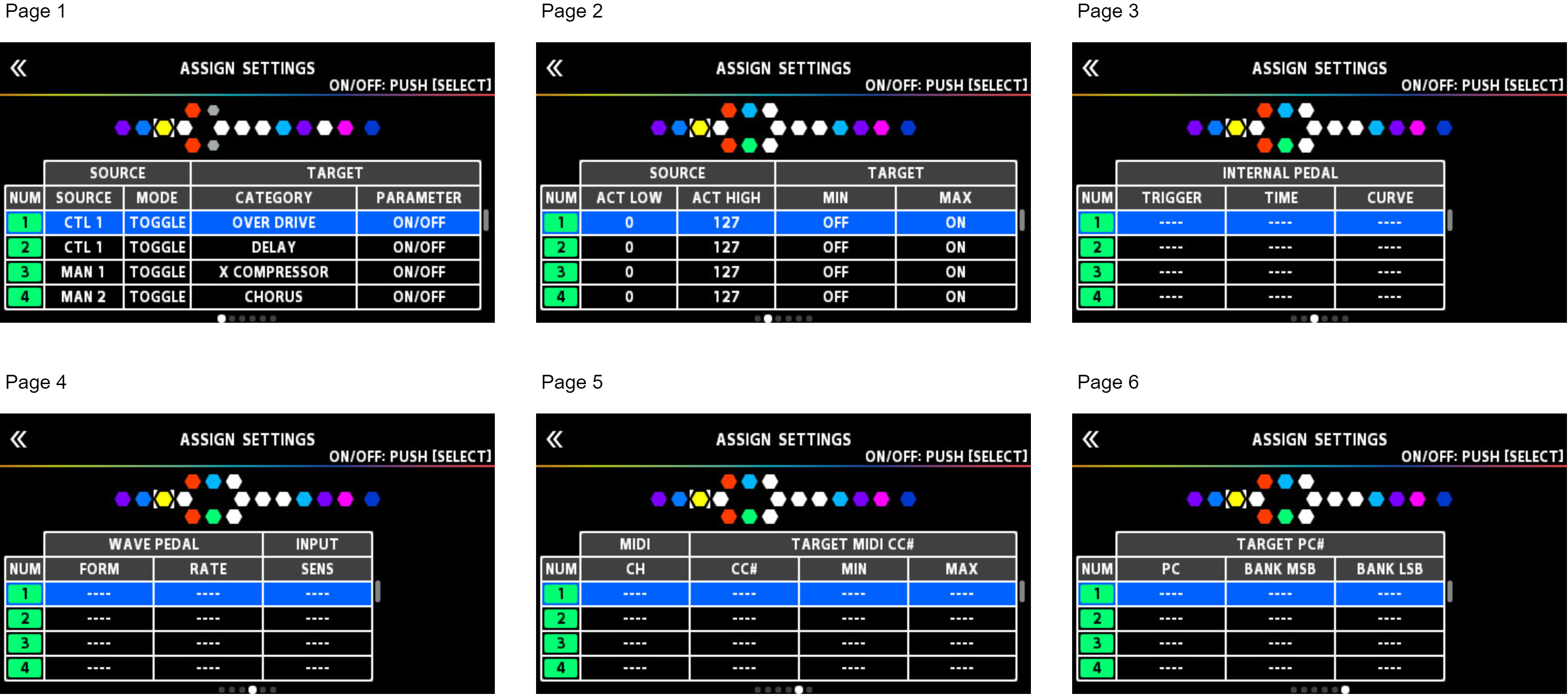
Press the [SELECT] knob to turn the selected ASSIGN NUMBER (NUM) on/off.
| Parameter | Value | Explanation | ||
|---|---|---|---|---|
| SW | OFF, ON | Turns the ASSIGN 1–20 on/off. | ||
| TARGET | TARGET | This selects the parameter to be changed. | ||
| MIN | This sets the minimum value for the range in which the parameter can change. The value differs depending on the parameter assigned for TARGET parameter. |
|||
| MAX | This sets the maximum value for the range in which the parameter can change. The value differs depending on the parameter assigned for TARGET parameter. | |||
| SOURCE |
SOURCE | NUM 1–NUM 4 | Assigns the number switches [1]–[4] on this unit when set to memory mode. | |
| MAN 1–MAN 4 | Assigns the number switches [1]–[4] on this unit when set to manual mode. | |||
| CUR NUM | Assigns the same number switch as the selected memory number. | |||
| BANK à | Assigns the GX-100’s BANK [Ç] switch. | |||
| BANK á | Assigns the GX-100’s BANK [É] switch. | |||
| CTL 1, CTL 2 | Assigns the GX-100’s [C1]–[C2] switch. | |||
| CTL 3, CTL 4 | Assigns the external footswitch connected to the CTL 3, 4/ EXP 2 jack. | |||
| EXP 1 SW | Assigns the GX-100’s [EXP 1] switch. | |||
| EXP 1 | Assigns the GX-100’s expression pedal. | |||
| EXP 2 | Assigns the external expression pedal connected to the CTL 3, 4/ EXP 2 jack. | |||
| INT PDL | Assigns the internal pedal. | Refer to “Virtual Expression Pedal System (Internal Pedal / Wave Pedal)”. | ||
| WAVE PDL | Assigns the wave pedal. | |||
| INPUT | The assigned target parameter will change according to the input level. | |||
| CC# 1–31, 64–95 | Control Change messages from an external MIDI device. | |||
| MODE | MOMENT | The normal state is Off (minimum value), with the switch On (maximum value) only while the footswitch is depressed. | ||
| TOGGLE | The setting is toggled On (maximum value) or Off (minimum value) with each press of the footswitch. | |||
| ACT LOW | 0–126 | You can set the controllable range for target parameters within the source’s operational range. Target parameters are controlled within the range set with ACT LOW and ACT HIGH. You should normally set ACT LOW to 0 and ACT HIGH to 127. |
||
| ACT HIGH | 1–127 | |||
| SENS | 0–100 | This adjusts the input sensitivity when INPUT is selected for SOURCE. | ||
| INTERNAL PEDAL |
TRIGGER *1 |
MEMORY CHANGE | This is activated when memory is selected. | |
| EXP1 PDL-LOW | This is activated when the GX-100’s expression pedal is set to the minimum position. | |||
| EXP1 PDL-MID | This is activated when the GX-100’s expression pedal is moved through the middle position. | |||
| EXP1 PDL-HIGH | This is activated when the GX-100’s expression pedal is set to the maximum position. | |||
| EXP1 SW | This is activated when the [EXP 1] switch is operated. | |||
| NUM1–NUM4 | This is activated when the [1]–[4] switch is operated. | |||
| CUR NUM | This is activated when you operate the same number switch as the selected memory number. | |||
| EXP 2 | This is activated when an external expression pedal connected to the CTL 3, 4/ EXP 2 jack. | |||
| CTL 1, CTL 2 | This is activated when the [C1]–[C2] switch is operated. | |||
| CTL 3, CTL 4 | This is activated when an external footswitch connected to the CTL 3, 4/ EXP 2 jack is operated. | |||
BANK à |
This is activated when the BANK [Ç] switch is operated. | |||
| BANK á | This is activated when the BANK [É] switch is operated. | |||
| CC#1–31, 64–95 | This is activated when a control change is received. | |||
| TIME *1 | 0–100 | This specifies the time over which the internal pedal will move from the toe-raised position to the toe-down position. | ||
| CURVE *1 | LINEAR |
|
||
| SLOW RISE |
|
|||
| FAST RISE |
|
|||
| WAVE PEDAL | FORM *2 | SAW |
|
|
| TRI |
|
|||
| SINE |
|
|||
| RATE *2 | 0–100, BPM ŀ–Ō |
This determines the time spend for one cycle of the assumed EXP Pedal. | ||
|
||||
| MIDI | CH *3 *4 | SYSTEM | Transmits a message on the MIDI channel specified by the parameter TX CHANNEL in “MIDI SETTING”. | |
| 1–16 | The message is transmitted on the specified MIDI channel. | |||
| TARGET MIDI CC# *3 | CC# | 0–127 | The message is transmitted using the specified controller number. | |
| MIN | 0–127 | Selects the minimum value of the transmitted CC# message. | ||
| MAX | 0–127 | Selects the maximum value of the transmitted CC# message. | ||
| TARGET MIDI PC# *4 |
PC# | 1–128 | Specifies the program number that is transmitted. | |
| MSB | OFF, 0–128 | Specifies the bank select MSB that is transmitted. If this is OFF, the bank select MSB is not transmitted. | ||
| LSB | OFF, 0–128 | Specifies the bank select LSB that is transmitted. If this is OFF, the bank select LSB is not transmitted. | ||
*1 The INTERNAL PEDAL TRIGGER, INTERNAL PEDAL TIME, and INTERNAL PEDAL CURVE parameters are enabled when the SOURCE parameter is set to INT PEDAL.
*2 The WAVE PEDAL FORM and WAVE PEDAL RATE parameters are enabled when the Source parameter is set to WAVE PEDAL.
*3 The MIDI CH, TARGET MIDI CC# parameters are enabled when the TARGET is set to MIDI CC.
*4 The MIDI CH, TARGET MIDI PC# parameters are enabled when the TARGET is set to MIDI PC.
